Alte Grube Velsen 16
D-66127 Saarbrücken
Mo – Fr 8.00 – 10.00 Uhr & 15.00 – 17.45 Uhr
Sa 7.00 – 14.45 Uhr
Mo – Fr 7.00 – 18.15 Uhr
Sa 7.00 – 14.45 Uhr
+49 (0)6898 946-0
info@ava-velsen.de
Alte Grube Velsen 16 | D-66127 Saarbrücken
+49 (0)6898 946-0 | info@ava-velsen.de
Mo – Fr 8.00 – 10.00 Uhr & 15.00 – 17.45 Uhr
Sa 07.00 – 14.45 Uhr
Mo – Fr 07.00 – 18.15 Uhr
Sa 07.00 – 14.45 Uhr
Alte Grube Velsen 16
D-66127 Saarbrücken
+49 (0)6898 946-0
info@ava-velsen.de
Mo – Fr 8.00 – 10.00 Uhr &
15.00 – 17.45 Uhr
Sa 07.00 – 14.45 Uhr
Mo – Fr 07.00 – 18.15 Uhr
Sa 07.00 – 14.45 Uhr
Alte Grube Velsen 16 | D-66127 Saarbrücken
+49 (0)6898 946-0 | info@ava-velsen.de
Mo – Fr 8.00 – 10.00 Uhr & 15.00 – 17.45 Uhr, Sa 07.00 – 14.45 Uhr
Mo – Fr 07.00 – 18.15 Uhr, Sa 07.00 – 14.45 Uhr
Alte Grube Velsen 16 | D-66127 Saarbrücken
+49 (0)6898 946-0 | info@ava-velsen.de
Mo – Fr 8.00 – 10.00 Uhr & 15.00 – 17.45 Uhr, Sa 07.00 – 14.45 Uhr
Mo – Fr 07.00 – 18.15 Uhr, Sa 07.00 – 14.45 Uhr
Technology
Technical Data
- Annual throughput: 255,000 tons max.
- Bunker volume: approx. 9,000m³ = 6,000t non-recyclable waste
- Storage capacity: 7-8 days
- Incineration units 2 lines @ 17.65t/h max.
- Design calorific value 10,000kJ/kg
- Grate system moving grate
- Boiler 4-pass boiler
- Flue gas purification 4 stages per line, free of waste water
- Live steam generation 2 x 48t/h at 40/400 (bar/ºC)
- Turbine output 20.8MW
- Waste gas 2 x 87,000m³/h (i.N.)
Procedure
Velsen Waste-to-Energy Heating Plant
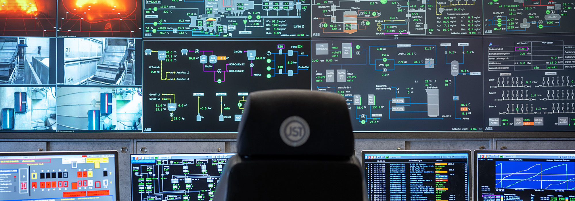
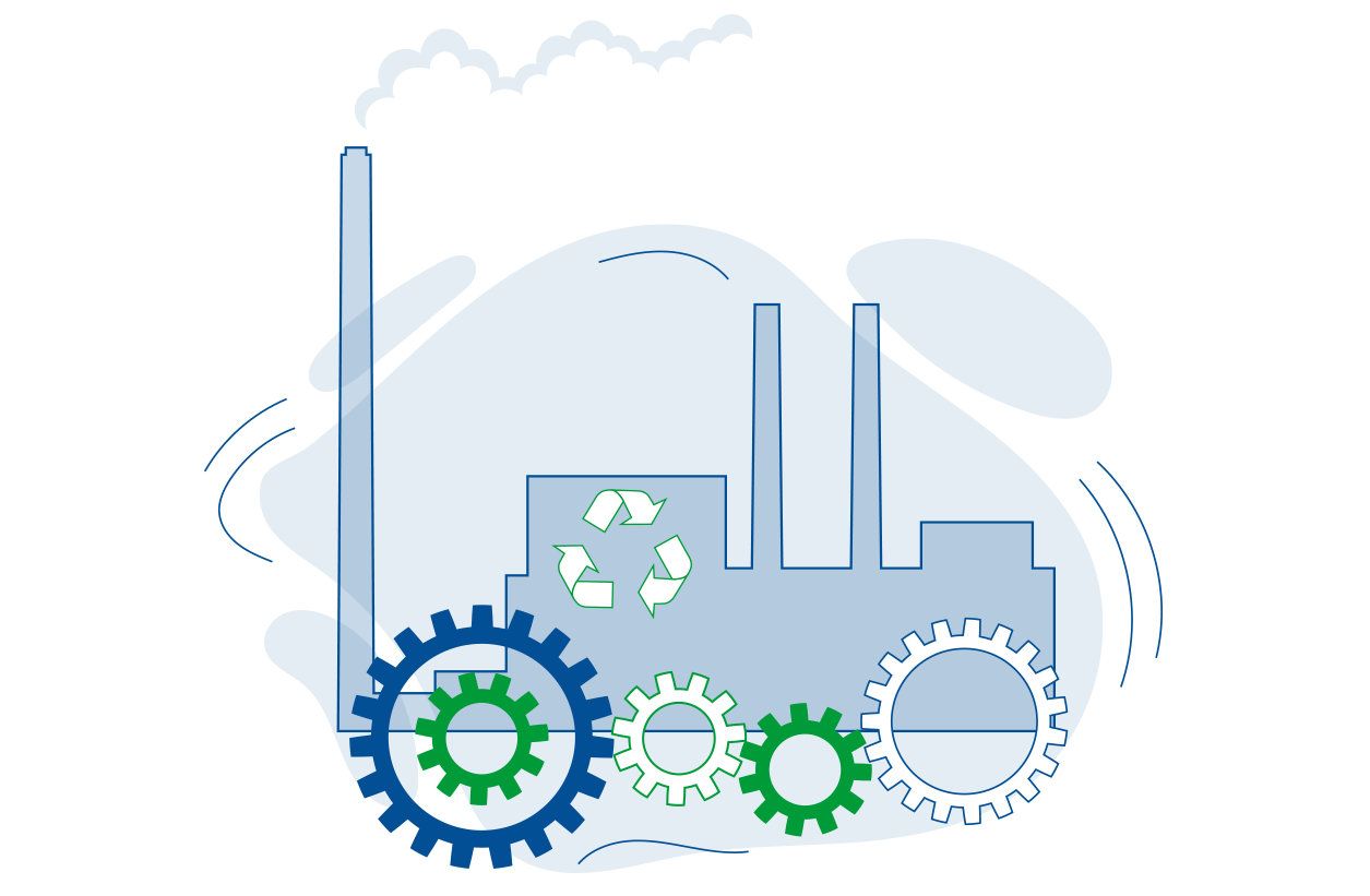
With the two incineration units installed in the Velsen waste-to-energy heating plant, a total of 30 tons of waste per hour can be thermally treated. The resulting flue gas is channeled into the 4-stage flue gas purification system.
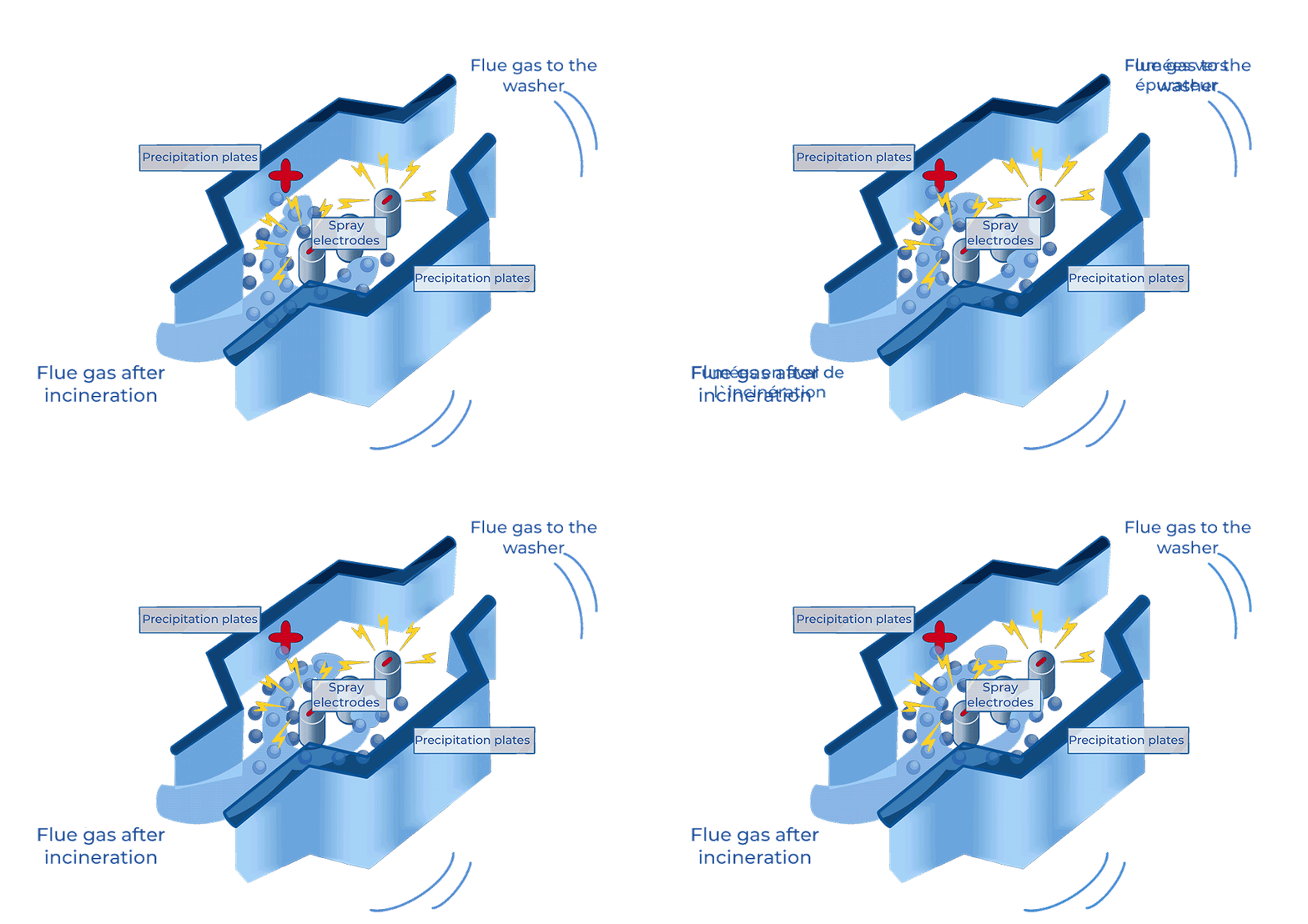
The gas then goes through dust removal, flue gas scrubbing, denitrification, and removal of dioxins.
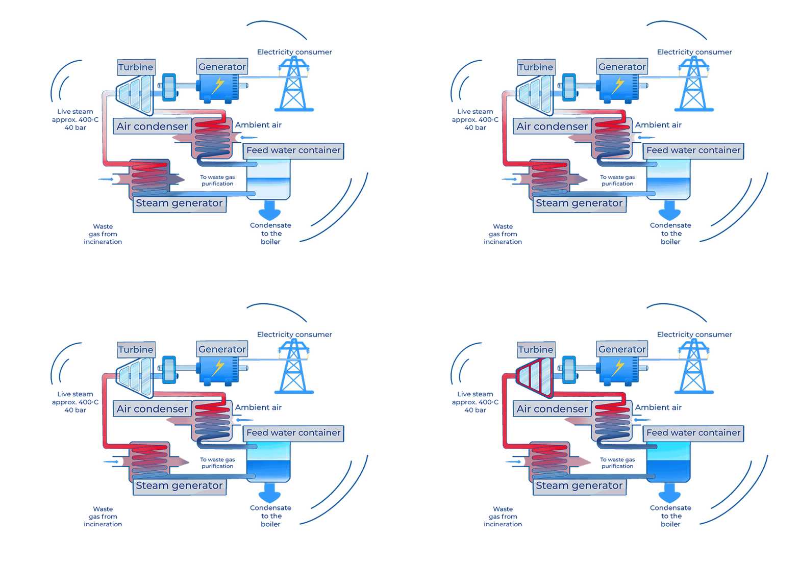
The energy released during incineration is transferred to the water/steam cycle. The steam is used for the generation of electricity. Part of the generated steam covers the plant's own requirements. The generated electricity supplies 30,000 households.
Acceptance of Waste
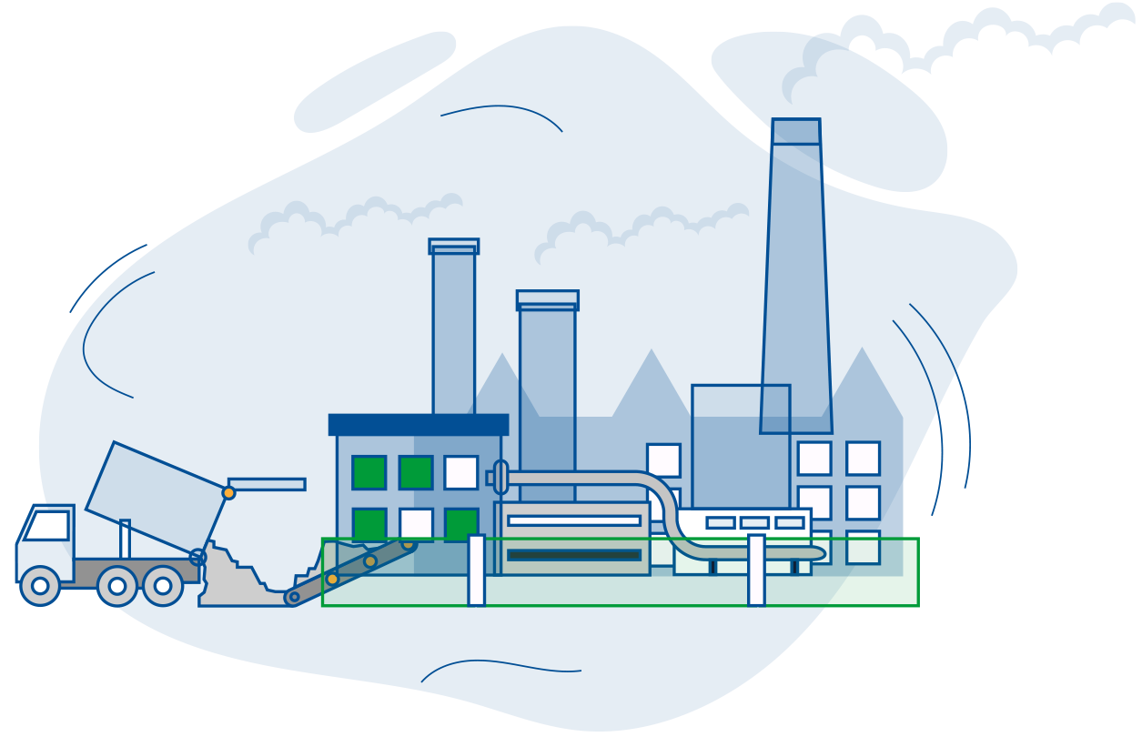
All waste is transported to the waste-to-energy plant on bin lorries and weighed electronically. Via one of the seven dumping points, the bin lorries then discharge their waste into the waste bunker in a closed hall. All delivered bulky waste is shredded separately in a bulky waste shredder and temporarily stored in the waste bunker as well.
The waste bunker is separated from the delivery hall by lockable dumping points. The extraction of the required combustion air from the waste bunker creates a negative pressure and thus prevents odours from spreading. Up to 6,000 tons of waste can be stored temporarily in the waste bunker. This equates to an incineration capacity of between 7 and 8 days. In the waste bunker, the waste is homogenised using the two waste grabbers with a capacity of 8m³ each.
This is necessary in order to achieve a fuel mixture that is as homogenous as possible. The waste grabbers convey the waste onto the two incineration lines
Thermal Treatment
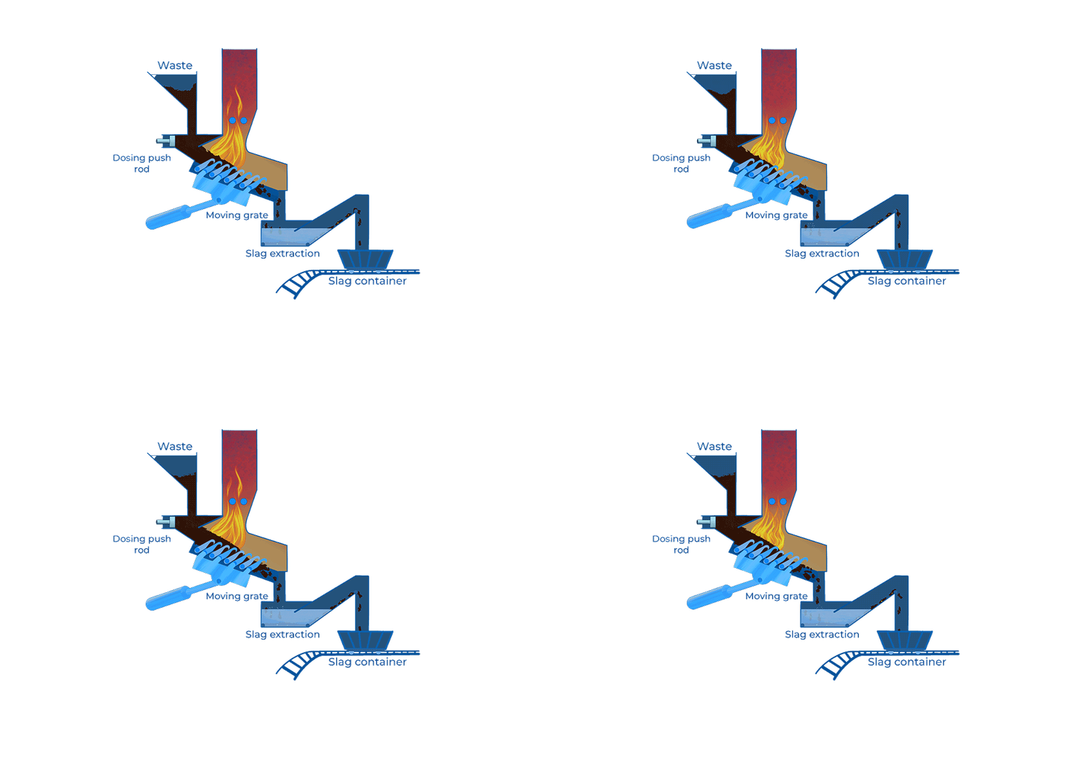
Using a dosing push rod, the waste is deposited on the grates via the feed hoppers of the two incineration lines. On the inclined grate surface (18° angle), the waste is first dried, then degassed, and subsequently incinerated. In a water-filled wet slag extraction unit, the remaining incineration residue (slag) is cooled down to ambient temperature and filled into slag containers. Fuel oil burners are only used when the incineration lines are started up. In normal operation, the waste incineration is self-sustaining. If necessary, the required minimum incineration temperature of 850°C is ensured by switching on oil-fired auxiliary burners.
Flue gas purification
4-stage flue gas purification
The hot flue gases produced during incineration are fed into the 4-stage flue gas purification system. Here, the various pollutants are removed in 4 consecutive process stages.
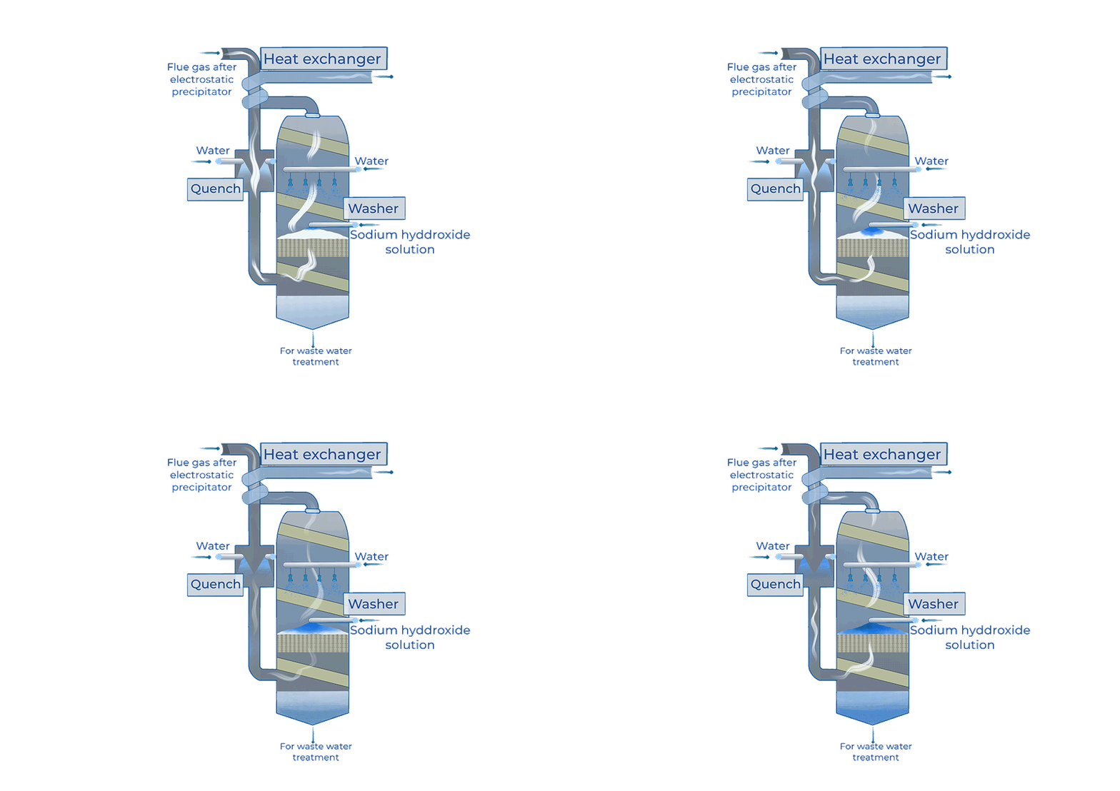
2nd stage: Flue gas scrubbing
First, the flue gas is cooled down to approximately 60 degrees Celsius by intensive spraying with water in the so-called Quench. During this process, inorganic fluorine, chlorine, and heavy-metal compounds in particular are removed from the flue gases and dissolved in the washing water. The addition of caustic soda to the washing water then creates favourable conditions for highly effective sulfur dioxide separation. Specially shaped plastic parts also ensure intensive contact between the washing water and flue gas, resulting in a particularly high degree of cleaning. In order to separate the fine dust, the flue gas flow in the scrubber is finally divided into a large number of small nozzles and again intensively sprayed with water. That way, residual inorganic compounds and harmful gases that are still present are additionally separated off.
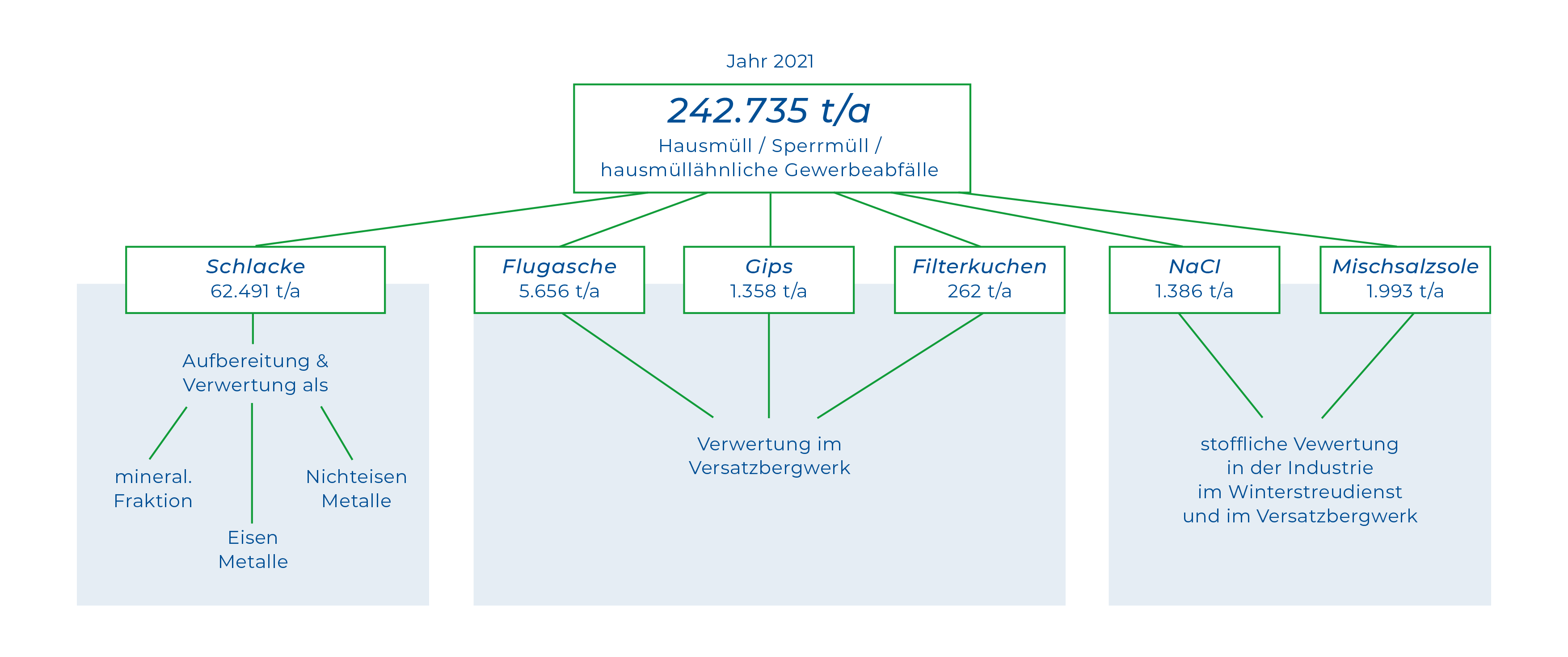
The contaminated washing water is fed into a treatment plant. The gypsum formed from the sulfur dioxide is filtered off and stored in containers ready for transport. The heavy-metal compounds dissolved in the washing water are converted into a solid form by adding chemicals, and also filtered out and stored in containers for removal. The salts remaining in the flue gas scrubbing water are concentrated in the evaporation plant by evaporating the water content. Solid salt and a 30% salt solution, the so-called mixed brine, result from the washing water treatment. Solid salt is kept in containers and mixed brine in tanks, ready for transport.
As the condensate is returned to the washing water circuit, the process sequence in the flue gas scrubber is free of waste water.
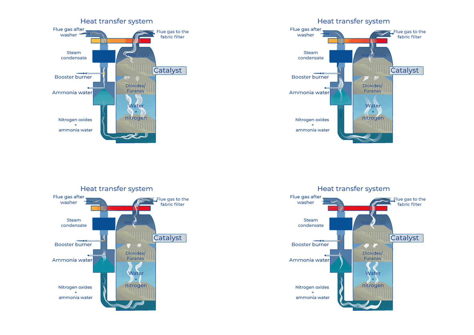
3rd stage: The catalyst
For the optimum disintegration of nitrogen oxides as well as dioxins and furans, the catalyst requires an operating temperature of 240 degrees Celsius. The operating temperature is reached by means of a steam-heated heat exchanger, without the use of primary energy. Before the flue gas enters the catalytic converter, it is mixed with ammonia water. This converts the nitrogen oxides into nitrogen and water vapour in the first catalyst section. In the second catalyst section, dioxins, furans, and other organic compounds are converted into water, carbon dioxide, and hydrochloric acid. When the flue gas flow leaves the catalyst, a large part of the dioxins and furans will have already been destroyed here.
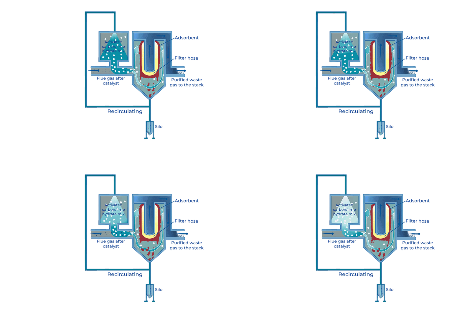
4th stage: The fabric filter
At this stage, the residual amounts of dioxins, furans, and heavy metals as well as any other organic and inorganic pollutants are removed. For this purpose, a mixture of hydrated lime and activated carbon (adsorbent) is blown into the flue gas flow and, after the pollutants have accumulated on the adsorbent, is removed again from the flue gas in the fabric filter. The adsorbent sticks to the outer walls of the filter bags. The filter bags are cleaned regularly.
Use of energy
In the incinerator, the incineration heat is transferred into the steam cycle with a high degree of efficiency. Part of the generated steam covers the internal requirements of all heat consumers of the plant. Most of the steam is used to generate electricity.
The hot high-pressure steam (400 degrees Celsius, 40 bar) drives a turbine that is connected to a generator to produce electricity. The electricity surplus of approx. 85,000MWh annually is fed into the public grid. This equates to the demand for electricity of around 30,000 households.
Input / Output
 English

